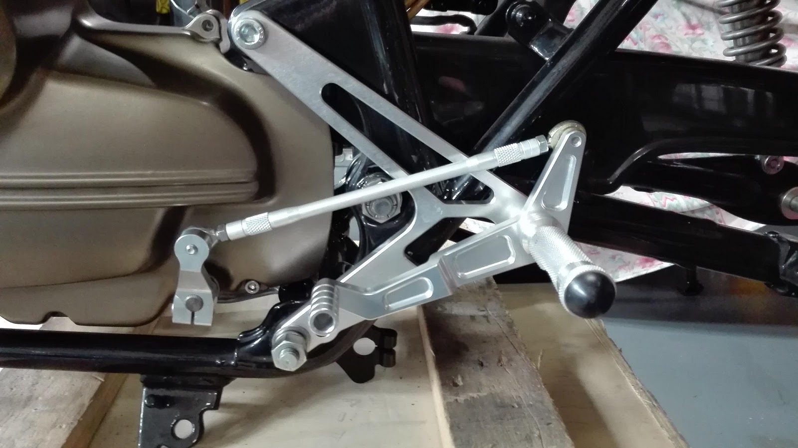
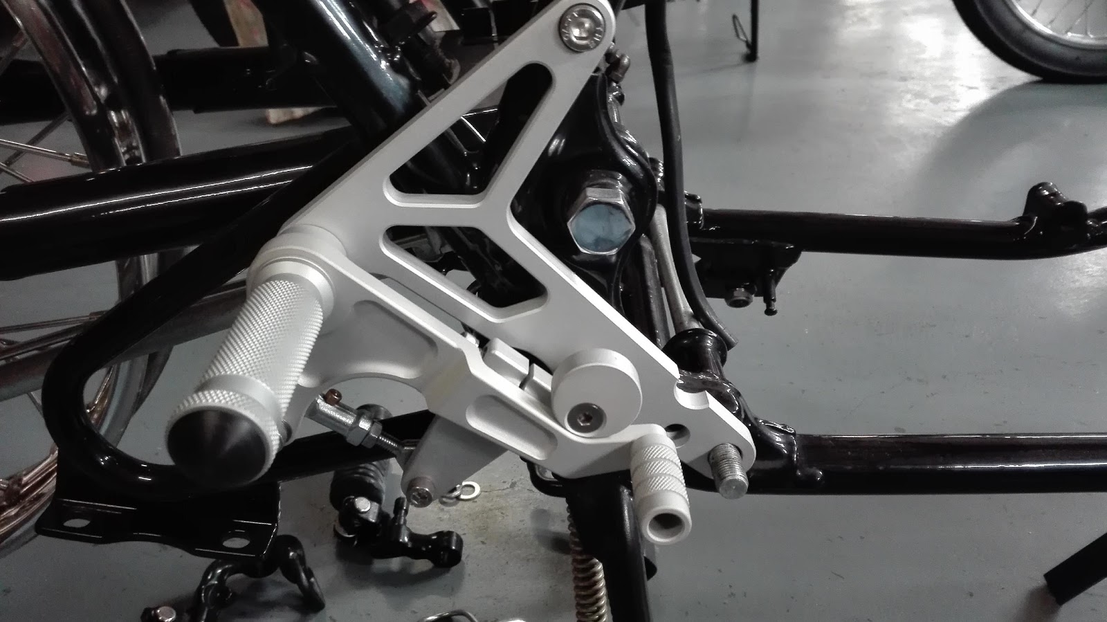
Fitting of your new TTR400 rearsets. Part # 400-100
1. Remove the OEM footrest assemblies, including the rear brake lever. You will re-use the 2 M12 nuts and spring washers.
2. Remove the the upper rear motor mount bolt. You will re-use the M10 nut and the LH spacer.
3. Remove the lower of the 2 M8 flanged OEM bolts from the rear RH motor mount bracket.
4. Install the LH side Rear set assembly to the frame. Slide in the new top motor mount bolt don't forget the motor spacer. Fit the M12 Nut and washers on lower motor mount bolt hand tight.
5. Install the new gearbox bracket , see photo. Fit the rod end to the gearbox bracket. If your swing arm nut is fitted to the LH side, then you may need to fit rod end to the out side of the gearbox bracket. See photo. If the nut is on the RH side, fit rod end to the inside of the gearbox bracket, Adjust the gear shift rod for the desired shift lever position. Correct installation will have even rod end threads screwed into the shift rod and that the gearbox bracket does not contact the engine cover when engaging first gear. The best position for the shift lever rod end is on the inside as in the photo, even with the swing arm nut fitted on the left as in the photo. I fitted a spacer behind the top motor mount bolt of around 4-5mm thick.
6. Install the RH side brake assembly. (do not fit new brake bracket) Make sure you fit the new spacer to the lower motor mount bolt before fitting assembly. Fit the new M8x80 stainless cap screw to replace the OEM bolt removed in step 3. now tighten the lower M12 nuts with the washers in place, tighten the M8x80 bolt. Tighten the New upper motor mount bolt installed in step 4. first the M8 cap screw on the LH side and then re-fit battery earth cable and M10 OEM nut.
7. Fitting the brake lever bracket: remove the rod end assembly from the bracket, remove the brake lever adjustable stop. Put pressure on the splined OEM shaft (push forward) fit the new brake lever bracket to the splined shaft. See photo. Re fit the brake lever adjustable stop in the highest position (this should be correct position for lever) adjust the rod end assembly to the correct length with the brake lever touching the lever stop. There is a spacer on the lever end so the rod end assembly is fitted parallel. The rod end assembly are both right hand thread. When happy with the position and that the brake operates correctly, tighten all fasteners. *Do not use any Locktight* as if you have to remove at a later date this will damage the alloy threads.
8. Finally position the foot pegs with the cut outs at the bottom and tighten the M8 bolts.
9. Racing Use: Drill for lock wire the foot peg bolts. Also advisable to lock wire all the rod ends.


